Hybrid CGRA Systems
System Prerequisites
Use of hybrid systems requires: CGRA-ME framework RISC-V compiler
You may find the manual here.
The useage of the tools and example use of the entire flow can be found in Makefile under
hybrid_systemfolder. To use the compiler and the simulatior in Makefile, you will need to specify their path in Makefile or include them in your path.
Hybrid System Overview
Block Diagram for the hybrid system
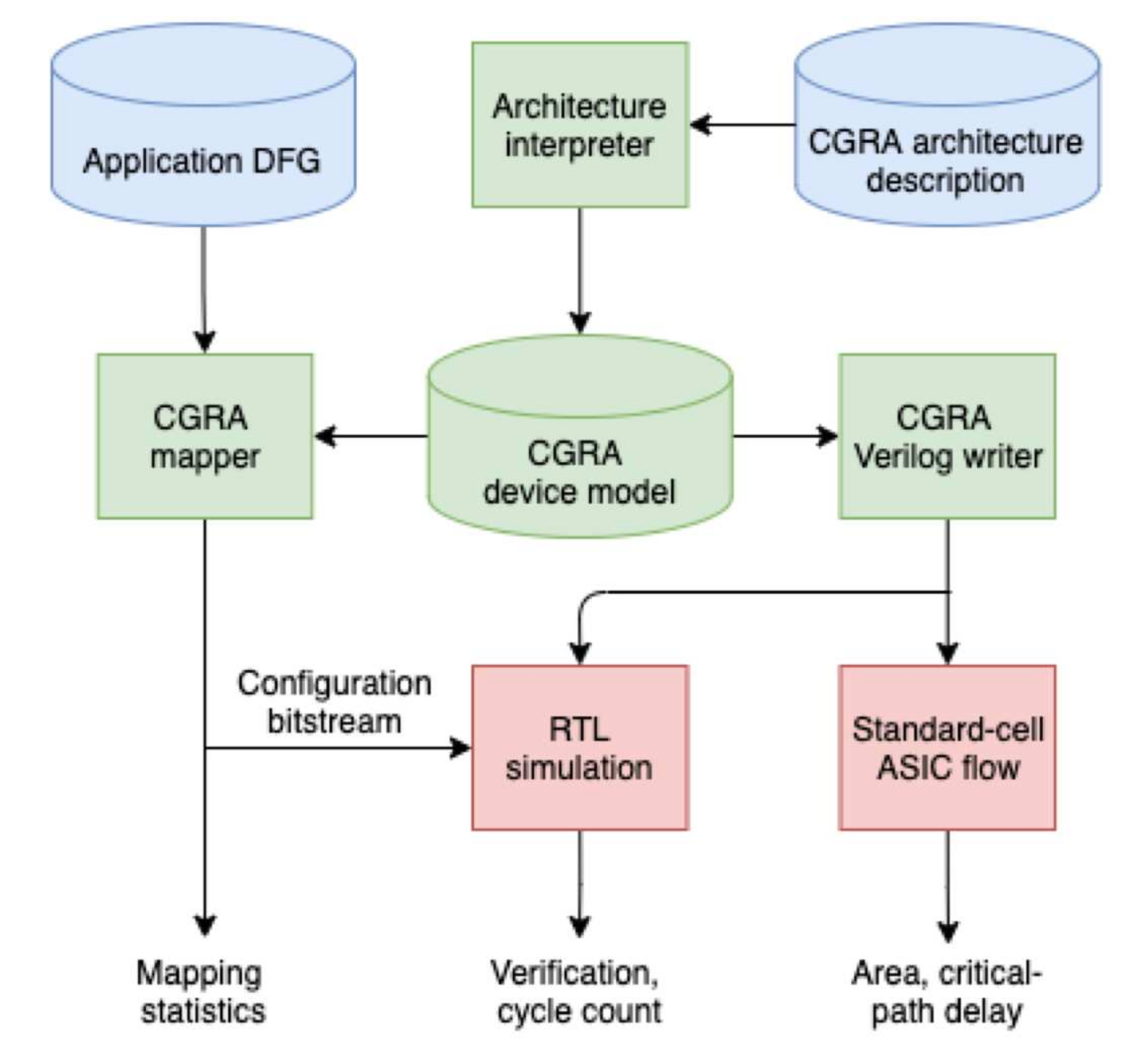
The blue boxes show the inputs to the framework:
a specification of a CGRA architecture through the C++ API.
an application dataflow graph (DFG). The DFG represents a compute-intensive kernel for CGRA acceleration.
The architecture specification is parsed to create an in-memory CGRA device model – the central green block in the diagram.
The mapper in CGRA-ME is architecture agnostic: it accepts the device model as input, as well as the application DFG, producing mapping statistics and a configuration bitstream for the modelled CGRA. The in-memory device model can also be fed to a Verilog RTL generator.
Hybrid connection
Communication
RISC-V processor and CGRA systems use two ways of communication: I/O ports and True dual-port memory. For I/O ports, memory-mapped register are used to write or read data using CGRA I/O ports. For memory, CGRA is able to communicate through all memory banks at the same time. RISC-V writes data to and reads data from a single memory bank each generation based on the memory address.
Starting/Stopping the CGRA
Two ways are possible for RISC-V processor to start and stop CGRA. The first is through a counter. RISC-V starts the CGRA by writing to the register connected to the enable signal of CGRA and write the number of cycles needed for the computations to a counter embedded in the Control Unit. The counter will count down and siganl the processor to stop the CGRA when it decreases to 0. The other way is to use memory data as the indicator of the end of the computations. CGRA compares the input data from memory to the specific memory data and output to one of its output ports when the memory data is detected. The processor should store this data to the memory after all computations are done. When the output port shown value 1, it means the computation is finished. RISC-V processor fetch the output from the port and stop CGRA.
Apart from memory-mapped registers for I/O ports, four memory-mapped registers are used for communication inside Control Unit.
Functional ports: - [1] A counter port is used for the first method to start and feed the cycle number to the counter. - [2] A endport is used for the second method to tell the system that memory data is used and to start CGRA. - [3] A select port for the second method is to let users to decide which output port is used for ending signal. - [4] A reset port is used for RISC-V processor to reset CGRA
CGRA architecture
CGRA takes in bitstream generated from DFG files for applications. CGRA comes with a command line option to take in a text file that can fix operands in DFG files to specific nodes in CGRA. For example: i4_load0:mem_2 i4_load1:mem_3 i4_load2:mem_1 i4_store1:mem_0 More examples can be find in folder hybrid_system/cgra/bitstream
RISC-V processor
RISC-V processor take in hex files that are compiled by RISC-V GNU tools as instruction set. To use memory data to stop CGRA, RISC-V processor need to select the right output port same as the CGRA node it fixes in the text file. It also needs to write the ending data of the computation to the right memory bank which fixes the load operand in DFG file used to compare the data
Automation system
The CGRA-ME framework generates the following components necessary for running the hybrid system - [1] cgrame.v: CGRA architecture Verilog file decided by the input CGRA architecture description - [2] testbench.v: Bitstream Verilog file decided by * Input CGRA architecture description * DFG file for application * Text file for fixing ports - [3] control.sv: Connection System Verilog file decided by the input CGRA architecture description - [4] hybrid.h: Auxiliary header file for helping users to write assembly codes, decided by the input CGRA architecture description. .. NOTE:: To use the hybrid system, two file are required the provide by the users: a DFG file for the application and an assembly file for the RISC-V processor.
Examples to write a DFG for using memory data to start or stop CGRA is shown in folder cgra-me/hybrid_system/cgra/bitstream/data/. Note that you will need a constant(-1 in the example) to compare with and an output port(end in the example) to output the comparing reuslt(1 for true and 0 for false).
Examples to write a DFG for using counter to start or stop CGRA is shown in folder cgra-me/hybrid_system/cgra/bitstream/counter/. No extra implementation in this case since the processor is supposed to input the counter number.
Examples to write an assembly code for using memory data to start or stop CGRA is shown in folder /cgra-me/hybrid_system/hybrid_conn/firmware/data/. Note that you will need to write data which shows the end of the computation to the corresponding memory bank. The memory bank is the bank which load operand is used to detect the ending data(decided by both DFG file and the text file for fixing port). Also you need to specify which port is used to show the comparison result using selport in the header file. Note that this port should also corresponds to the port in the fixing-port text file to map the ending node(names end in our example). The I/O ports are ordered in the same way as printed by --print-mrrg command and can be selected using integer numbers in the assembly code.
Examples to write an assembly code for using counter to start or stop CGRA is shown in folder /cgra-me/hybrid_system/hybrid_conn/firmware/counter/. Note that the counter number should be loaded to counter address as specified in the example assembly code. Users need to know how many cycles are required to finish the computations including latency.